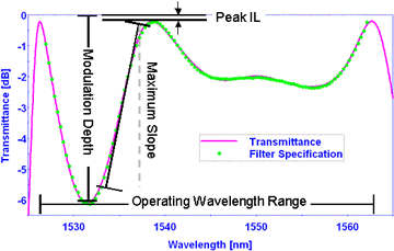
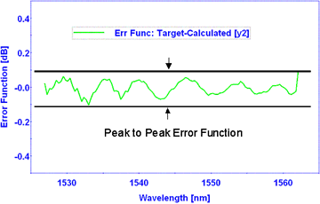
Gain Flattening Filter (GFFs), also known as gain equalizing filters, are used to flatten or smooth out unequal signal intensities over a specified wavelength range. This unequal signal intensity usually occurs after an amplification stage (e.g., EDFA and/or Raman) . Typically, GFFs are used in conjunction with gain amplifiers to ensure that the amplified channels all have the same gain. The quality of a GFF is best described by the peak-to-peak error function (PPEF) because it represents the maximum flatness of the transmitted signal. The PPEF is calculated by comparing the spectral performance of the manufactured filter to the target curve specification. In general, the factors that determine the minimum PPEF that can be achieved are the maximum slope and the smoothness of the target curve. Some applications require multiple flattening regions or the addition of pass band outside the flattening region; these may increase the complexity of the filter. 

[nice-button link=”/product-category/telecom/gain-flattening/”] GFF Filters[/nice-button]
Operating Wavelength Range
The wavelength domain specified in the gain equalizing target typically defines the operating range [lStart, lEnd]
Peak Insertion Loss (IL) [dB]
Peak insertion loss is the value of maximum transmission (at lMax) within a specified range. Typically the specified range is the entire operating range.
Peak IL = T(lMax) [dB]
e.g. Peak IL < 0.1 dB within operating range
Modulation Depth [dB]
The modulation depth is defined as the difference between the maximum transmission (TMax) [dB] and the minimum transmission value (TMin) [dB] within the operating wavelength range, i.e.,
Modulation Depth [dB] = TMax [dB] – TMin [dB]
Maximum Slope [dB/nm]
The slope curve is generated by calculating the slope between adjacent target points. The maximum value of this calculation over all points within the operating range is the maximum slope, i.e.,
Maximum slope = Max{ ( T(li)[dB] – T(li-1)[dB] )/ (li – li-1) }, i=1,2.3,…N
Error Function [dB]
The difference between the measured (TMeasured) [dB] and target (TTarget) [dB] transmittance points on the gain equalizing curve defines the error function (EF), i.e.,
EF(li) [dB] = TTarget(li) [dB] – TMeasured(li) [dB]
Peak-to-Peak Error Function (PPEF) [dB]
The peak-to-peak error function (PPEF) is a single valued specification defined as the difference between the maximum error function (EFmax) and the minimum error function (EFmin), i.e.,
PPEF [dB] = EFmax [dB] – EFmin [dB]
e.g. PPEF < 0.4 dB
Polarization Dependent Loss (PDL) [dB]
Polarization Dependent Loss (PDL) can be defined as the maximum change observed in transmittance or reflectance at a given wavelength as the light is cycled through all possible polarization states. The PDL can be calculated based on the difference between the s- and p-polarization states of light, i.e.,
Transmittance PDL(l) [dB] = Ts(l) [dB] – Tp(l) [dB]
GFF Shape Factor
The shape factor yields a quick estimate of the complexity of a GFF curve specification. It is defined as:
Shape Factor = maximum slope / PPEF.
Note: The shape factor provides only a relative measure of the complexity of a GFF filter.
Substrate Etalon Ripple Effect [dB]
With coherent light, any type of filter can act as a Fabry-Perot etalon if the two surfaces of the filter are sufficiently parallel and if the secondary surface of the filter is not anti-reflection (AR) coated. If this is the case, then there will be an etalon ripple superimposed on the desired filter shape. For a substrate thickness of 1 mm, the resultant ripple will have a period of ~0.8 nm at a wavelength of 1550 nm. The magnitude of the ripple will depend on the reflectance of the two sides of the filter and the substrate parallelism. This etalon ripple can be minimized by introducing a sufficient wedge angle (> 0.4 degs) or by depositing a very good AR coating on the secondary surface.
[nice-button link=”/product-category/telecom/gain-flattening/”] GFF Filters[/nice-button]


